잔글편집 요약 없음 |
잔글편집 요약 없음 |
||
| 13번째 줄: | 13번째 줄: | ||
[[파일:S-param.png]] | [[파일:S-param.png]] | ||
신호 손실(Loss)을 무시할 경우, 다음과 나타낼 수 있다. | |||
<math>V_1^-=S_{11}V_1^++S_{12}V_2^+</math> | <math>V_1^-=S_{11}V_1^++S_{12}V_2^+</math> | ||
2022년 4월 1일 (금) 01:58 판
Scattering Parameters (Scattering Matrix)
S-Parameters (S-Matrix)
개요
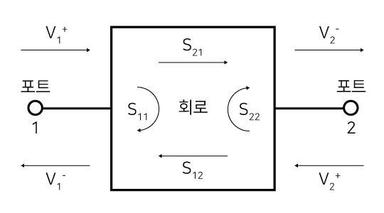
S-파라미터 또는 산란 계수는 RF 회로에서 포트 간의 입출력을 비교하는 수단으로 행렬(Matrix)을 통해 나타내며, 회로의 이득이나 반사 특성 등을 간편하게 해석할 수 있다.
S-파라미터를 측정하는 계측기를 네트워크 분석기라 한다.
정의
2개 포트를 가진 회로의 S-파라미터는 다음과 같이 4개의 원소로 나타낸다. 3개 포트일 경우 9개, 4개 포트일 경우 16개의 원소가 구성된다.
[math]\displaystyle{ S=\left[\begin{matrix}S_{11}&S_{12}\\S_{21}&S_{22}\\\end{matrix}\right] }[/math]
[math]\displaystyle{ S_{ab}=\frac{V_a^-}{V_b^+} }[/math]
신호 손실(Loss)을 무시할 경우, 다음과 나타낼 수 있다.
[math]\displaystyle{ V_1^-=S_{11}V_1^++S_{12}V_2^+ }[/math]
[math]\displaystyle{ V_2^-=S_{21}V_1^++S_{22}V_2^+ }[/math]
활용
이득
선형 이득에 한함.
전압 이득
[math]\displaystyle{ \text{V Gain}=S_{21}=\frac{V_2^-}{V_1^+} }[/math]
전력 이득
[math]\displaystyle{ P=\frac{V^2}{R} }[/math]이므로, 정격 임피던스에서 다음과 같이 나타낼 수 있다.
[math]\displaystyle{ \text{P Gain}=|S_{21}|^2 }[/math]
반사
정방향을 기준으로 함.
반사 계수
[math]\displaystyle{ \Gamma=S_{11}=\frac{V_1^-}{V_1^+} }[/math]
정재파비
[math]\displaystyle{ \mathrm{SWR}=\frac{1+|\Gamma|}{1-|\Gamma|}=\frac{1+|S_{11}|}{1-|S_{11}|} }[/math]
